
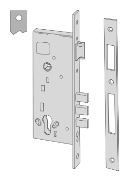
Lock and fitting dimensions
| Specifications | Dimensions from model documentation |
|---|---|
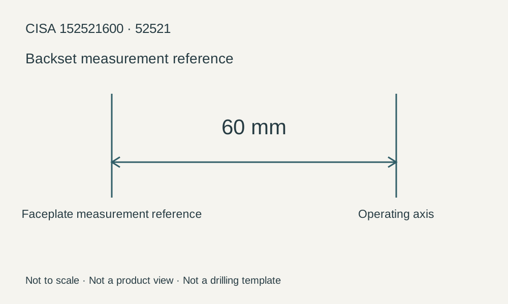
| Backset | 60 mm |
| Faceplate width | 22 mm |
| Centre distance | 85 mm |
Check the backset, centre distance, faceplate and mounting points against the specific model drawing.
Browse related directorySpecifications
- Backset
- 60 mm
- Faceplate ends
- Square ends
- Faceplate width
- 22 mm
- Centre distance
- 85 mm
- Bolt throws
- 2
- Bolt construction
- Three nickel-plated steel cylindrical bolts
- Latch
- Nickel-plated, flat and reversible
- Locking-point connection
- Central locking
- Case
- Galvanized steel
Construction and operation of this version
152521600 is an explicit ordering row in the 52521 series with backset 60 mm. The square-ended 22 mm faceplate and central-locking configuration determine the door-edge recess and locking-point layout. Three cylindrical bolts do not mean three independent locking points on the door frame; they are concentrated in the central lock body; additional top and bottom locking points require the corresponding connections.
How to check installation dimensions
This model's backset is 60 mm, the distance from the specified door-edge faceplate reference to the operating axis. Faceplate width, centre distance and external lock-body depth describe different directions and must not substitute for one another.
For replacement, record the old lock's full number, faceplate-end shape, inside and outside operating components and strike positions; when changing handing or linked rods, confirm interfaces according to the product instructions.
Limitations
- Extension rods and floor strikes listed as optional in the catalogue are not standard equipment for this item.
- Series certification and catalogue descriptions of fire or escape applications do not mean this model meets current requirements when installed in any door assembly.
- Check accessories against the corresponding model and installation instructions; Cylinders, rods and escutcheons listed as available on request are not standard equipment.
Sources
CISA 2026 English catalogue, PDF page 348 / printed page 344Manufacturer documents are provided in their original language.