
Lock and fitting dimensions
| Specifications | Dimensions from model documentation |
|---|---|
| Backset | 40 mm |
| Case thickness | 15.5 mm |
| Catalogue faceplate height | 2300 mm |
| Handle-to-cylinder centre distance | 85 mm |
| Spindle specification | 8 mm |
Check the backset, centre distance, faceplate and mounting points against the specific model drawing.
Browse related directorySpecifications
- Product series
- 49436
- Backset
- 40 mm
- Key system
- Euro-profile cylinder
- Body construction
- U-profile faceplate three-point geared mortise lock
- Case thickness
- 15.5 mm
- Faceplate cross-section
- 24 × 5 mm
- Faceplate shape
- U-profile
- Faceplate material
- Black-coated steel
- Catalogue faceplate height
- 2300 mm
- Upper-end adjustment
- 350 mm
- Lower-end adjustment
- 150 mm
- Handle-to-cylinder centre distance
- 85 mm
- Number of lateral bolts
- 3 units
- Latch adjustment range
- 11–17 mm
- Spindle specification
- 8 mm
- Bolt throw stages (original term Throws)
- 2
Construction and dimensional compatibility
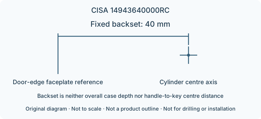
The fixed backset of 40 mm is measured horizontally from the door-edge faceplate to the cylinder centre axis; it is not the overall case depth. U-profile faceplate cross-section 24 × 5 mm, centre distance 85 mm, with 3 lateral bolts; Catalogue faceplate height 2300 mm.
Faceplate adjustment: upper end 350 mm, lower end 150 mm; these faceplate adjustments do not change the fixed 40 mm backset. Check the U-profile cross-section of the door-edge recess, upper and lower auxiliary-lock positions and centre distance together.
Also check the installation space inside the door leaf, strike position and plates on both sides. An identical fixed backset does not make different constructions directly interchangeable.
Limitations
- The parameter diagram explains only the measurement reference; it is not a product outline and must not be used for drilling or installation.
- Strikes, extension rods and other accessories offered on request in the catalogue are not standard equipment.
- Statements of lock-series suitability or certification are not promises of current compliance for any complete door configuration.
Sources
CISA 2026 English catalogue, PDF page 228 / printed page 224Manufacturer documents are provided in their original language.