
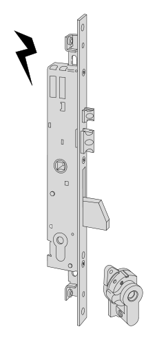
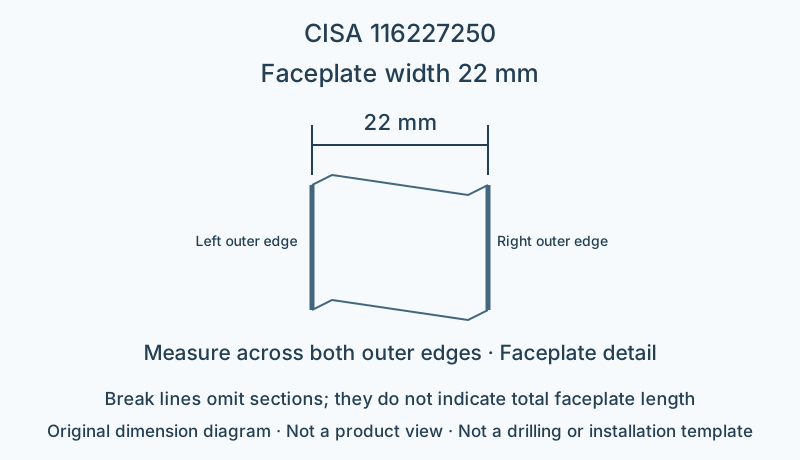
Lock and fitting dimensions
| Specifications | Dimensions from model documentation |
|---|---|
| Faceplate width | 22 mm |
| Centre distance | 85 mm |
Check the backset, centre distance, faceplate and mounting points against the specific model drawing.
Browse related directorySpecifications
- Series
- Rotating-bolt lock body
- Drive type
- Electric
- Locking construction
- Bolt and latch
- Backset E
- 25 mm
- Faceplate width
- 22 mm
- Faceplate profile
- Flat
- Faceplate material
- Stainless steel
- Cylinder interface
- Cruciform-key cylinder supplied
- Centre distance
- 85 mm
- Rated voltage
- 12 V AC
- Catalogue current consumption
- 3.1 A
- Latch adjustment
- 10.5–16.5 mm
- Additional locking-point connection
- Prepared for additional locking points; threaded pins connect extension rods
Installation dimensions and faceplate
This model has backset 25 mm, faceplate width 22 mm and centre distance 85 mm. Match the horizontal backset and vertical centre distance separately; door thickness cannot substitute for either.
Locking construction and matching components
The latch positions the door leaf on closing, while the bolt provides locking; during installation, separately check the latch contact surface, bolt strike opening and cylinder operating position. This model is prepared for additional locking points and uses threaded pins to connect extension rods; the catalogue's connecting rods and corner drives must be selected separately for the installation.
Match the 12 V AC supply and catalogue consumption of 3.1 A according to the installation instructions; do not substitute DC or assume continuous holding current.
Limitations
- The dimension diagram only explains the specified dimensional relationships; it is not a product outline, fixing-hole layout or installation template.
- Check strike openings, connectors and suitability for the complete door system against the manufacturer's installation documentation for this model.
Sources
CISA English catalogue, printed page 246 / PDF250 pageManufacturer documents are provided in their original language.