
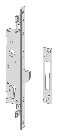
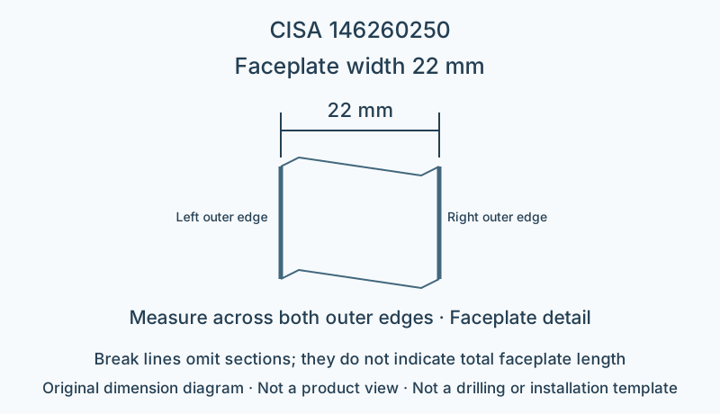
Lock and fitting dimensions
| Specifications | Dimensions from model documentation |
|---|---|
| Faceplate width | 22 mm |
Check the backset, centre distance, faceplate and mounting points against the specific model drawing.
Browse related directorySpecifications
- Series
- Rotating-bolt lock body
- Drive type
- Mechanical
- Locking construction
- Laminated-steel hook bolt
- Backset E
- 25 mm
- Faceplate width
- 22 mm
- Faceplate profile
- Flat
- Faceplate material
- Stainless steel
- Cylinder interface
- Euro-profile cylinder ordered separately
- Additional locking-point connection
- Prepared for additional locking points; threaded pins connect extension rods
Installation dimensions and faceplate
This model has backset 25 mm and faceplate width 22 mm. When checking the door-edge recess, also confirm the actual fixing-hole and cylinder positions.
Locking construction and matching components
The laminated-steel hook must engage the corresponding strike plate; selection should focus on strike position and engagement clearance; a strike opening for a straight bolt is not an appropriate substitute. This model is prepared for additional locking points and uses threaded pins to connect extension rods; the catalogue's connecting rods and corner drives must be selected separately for the installation.
This page describes a mechanically operated configuration; if a motor, hold-open device or electric strike is needed, check the applicable models for each accessory.
Limitations
- The dimension diagram only explains the specified dimensional relationships; it is not a product outline, fixing-hole layout or installation template.
- Check strike openings, connectors and suitability for the complete door system against the manufacturer's installation documentation for this model.
Sources
CISA English catalogue, printed page 250 / PDF254 pageManufacturer documents are provided in their original language.