
Specifications
- Series
- Rotating-bolt multipoint lock
- Drive type
- Mechanical
- Locking construction
- Lateral bolt and latch with upper and lower extension rods
- Backset E
- 30 mm
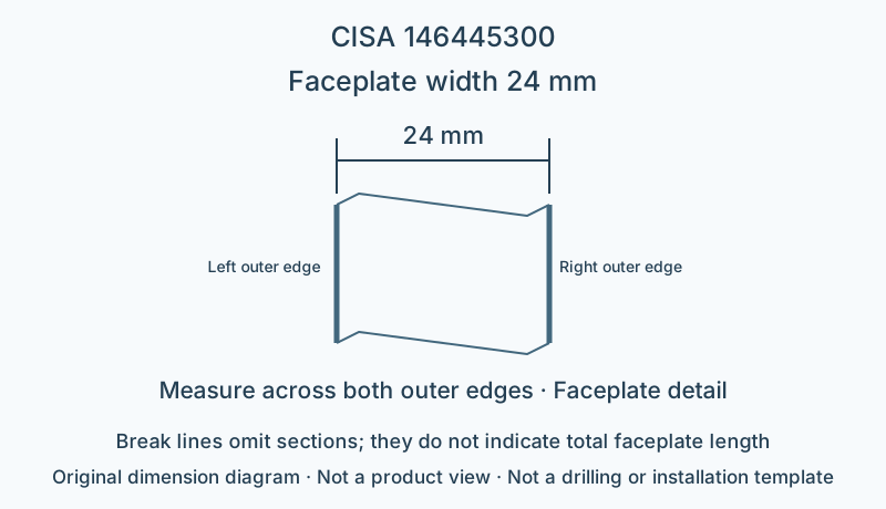
- Faceplate width
- 24 mm
- Faceplate profile
- U-profile
- Faceplate material
- Black-painted steel
- Cylinder interface
- Euro-profile cylinder ordered separately
- Centre distance
- 85 mm
- U-profile cross-section depth
- 7 mm
- Faceplate length
- 2600 mm
- Upper-end adjustment
- 650 mm
- Lower-end adjustment
- 150 mm
- Latch adjustment
- 11–17 mm
Installation dimensions and faceplate
This model has backset 30 mm, faceplate width 24 mm and centre distance 85 mm. Match the horizontal backset and vertical centre distance separately; door thickness cannot substitute for either. Faceplate length 2600 mm; permitted adjustment is 650 mm at the upper end and 150 mm at the lower end; these are faceplate configuration data; they do not permit arbitrary shortening or imply automatic compatibility with a door leaf of the same height. The depth of the U-profile cross-section differs from flat-plate thickness; check the door-edge recess against the cross-section.
Locking construction and matching components
The central lateral bolt and the upper and lower extension rods together form the locking system; the positions of the upper and lower rod ends cannot be replaced by the layout of lateral locking points at both ends.
This page describes a mechanically operated configuration; if a motor, hold-open device or electric strike is needed, check the applicable models for each accessory.
Limitations
- The dimension diagram only explains the specified dimensional relationships; it is not a product outline, fixing-hole layout or installation template.
- Check strike openings, connectors and suitability for the complete door system against the manufacturer's installation documentation for this model.
Sources
CISA English catalogue, printed page 241 / PDF245 pageManufacturer documents are provided in their original language.