
Specifications
- Series
- Multitop MATIC EXIT
- Drive type
- Mechanical
- Locking construction
- Automatic escape lock
- Backset E
- 45 mm
- Faceplate width
- 24 mm
- Faceplate profile
- U-profile
- Faceplate material
- Stainless steel
- Cylinder interface
- Euro-profile cylinder ordered separately
- Centre distance
- 92 mm
- U-profile cross-section depth
- 5 mm
- Faceplate length
- 2300 mm
- Upper-end adjustment
- 350 mm
- Lower-end adjustment
- 150 mm
- Main latch adjustment
- 10–16 mm
- Automatic reset sensor adjustment
- 9–15 mm
- Escape operating function
- A
- Handle spindle
- 8 mm
Installation dimensions and faceplate
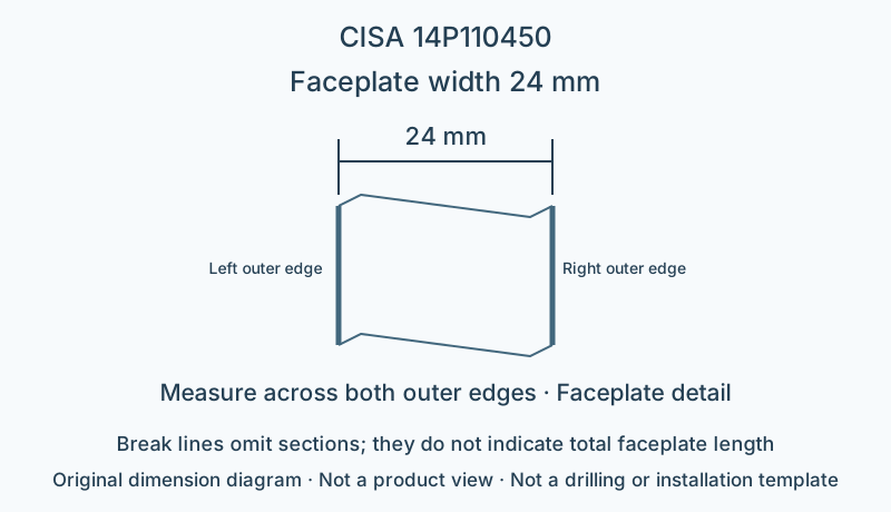
This model has backset 45 mm, faceplate width 24 mm and centre distance 92 mm. Match the horizontal backset and vertical centre distance separately; door thickness cannot substitute for either. Faceplate length 2300 mm; permitted adjustment is 350 mm at the upper end and 150 mm at the lower end; these are faceplate configuration data; they do not permit arbitrary shortening or imply automatic compatibility with a door leaf of the same height. The depth of the U-profile cross-section differs from flat-plate thickness; check the door-edge recess against the cross-section.
Locking construction and matching components
Function A: opening from inside through the matching escape device; the key operates latch and bolt from outside. The lock body must be paired with the devices, strike plates and door-leaf systems listed in the catalogue; the lock body alone does not establish certification of the complete door.
This page describes a mechanically operated configuration; if a motor, hold-open device or electric strike is needed, check the applicable models for each accessory.
Limitations
- The dimension diagram only explains the specified dimensional relationships; it is not a product outline, fixing-hole layout or installation template.
- Check strike openings, connectors and suitability for the complete door system against the manufacturer's installation documentation for this model.
Sources
CISA English catalogue, printed page 212 / PDF216 pageManufacturer documents are provided in their original language.