
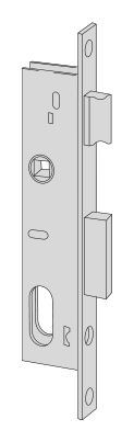
Lock and fitting dimensions
| Specifications | Dimensions from model documentation |
|---|---|
| Backset E | 25 mm |
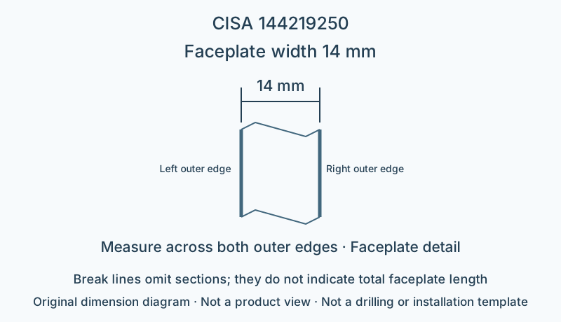
| Faceplate width | 14 mm |
| Centre distance | 69 mm |
Check the backset, centre distance, faceplate and mounting points against the specific model drawing.
Browse related directorySpecifications
- Construction
- Bolt-and-latch lock
- Backset E
- 25 mm
- Faceplate width
- 14 mm
- Case finish
- Galvanized
- Faceplate finish
- Galvanized
- Cylinder interface
- Oval cylinder, ordered separately
- Locking throws (Throws)
- 1
- Centre distance
- 69 mm
- Latch handing
- Non-handed
- Additional bolt projection
- 4.5 mm
- Key-operated latch
- Supported
Installation dimensions and interfaces
Catalogue backset E is 25 mm; faceplate width is 14 mm. Check the two dimensions separately; Measure faceplate width between the left and right outer edges; check the actual backset installation reference against the complete model drawing, without substituting door thickness.
The oval cylinder's profile and fixing method must be matched separately; a euro-profile cylinder is not a direct substitute.
Locking and operating conditions
This model has backset 25 mm; the key can operate the latch. Bolt locking has 1 throws; check the 69 mm centre distance together with the existing cylinder and handle positions.
Additional bolt projection is 4.5 mm; the door gap and strike plate must provide clearance for the projecting portion; this value is not the total bolt travel.
Limitations
- Check overall faceplate length, fixing-hole positions and actual strike-opening dimensions against the full installation drawing; the faceplate-width diagram is not a drilling template.
- The catalogue's electric-model voltage and current do not apply to the mechanical construction on this page; this page does not infer a fire rating or a security grade for the complete door.
Sources
CISA English catalogue, printed page 265 / PDF269 pageManufacturer documents are provided in their original language.