
Lock and fitting dimensions
| Specifications | Dimensions from model documentation |
|---|---|
| Adjustable backset | 50 / 60 / 70 / 80 mm |
Check the backset, centre distance, faceplate and mounting points against the specific model drawing.
Browse related directorySpecifications
- Construction
- Universal latch-only electric rim lock
- Adjustable backset
- 50 / 60 / 70 / 80 mm
- Rated supply
- 12 V AC
- Power
- 15 W
- Rated current
- 1.25 A
- Inside control
- Configurable as key, key plus button, or button only
- Backset type
- Four-position adjustment
- Outside cylinder
- Fixed outside cylinder Ø26×50 mm, supplied with adapter for conversion to a separate cylinder
- Strike vertical tolerance
- ±7 mm
- Handing
- Reversible
Functions and interfaces of this model
This model is reversible, with fixed outside cylinder Ø26×50 mm and an adapter for conversion to a separate cylinder; catalogue vertical tolerance between lock and strike plate is ±7 mm. The four backsets are adjustment positions of the same lock; check them together with door handing, power supply and strike-plate positioning; do not treat the AC value 12V as a DC rating.
Using adjustable backset for compatibility checks
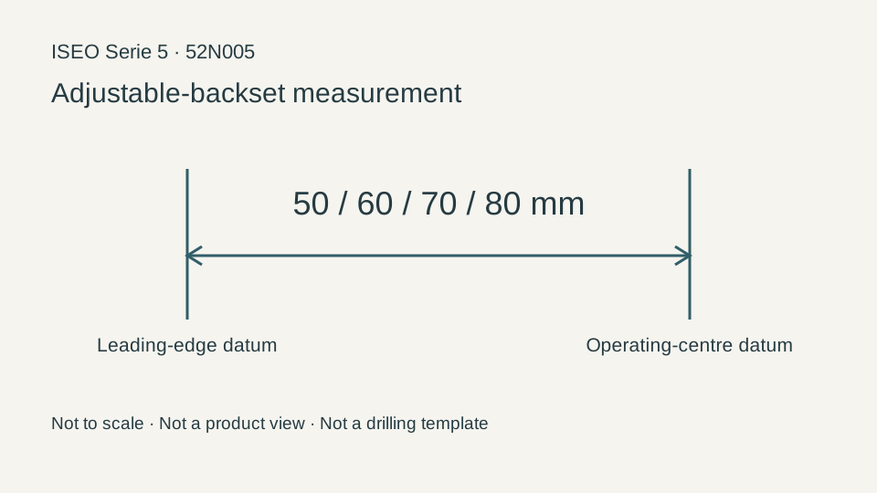
The catalogue records this model's adjustable backset as 50 / 60 / 70 / 80 mm. Backset is measured from the specified faceplate or door-edge reference to the operating centre. It describes a different direction from centre distance, lock-body width and door thickness; retain the original drawing's reference when measuring.
The selection checklist should also retain: adjustable backset 50 / 60 / 70 / 80 mm; Rated supply 12 V AC; Power 15 W; Rated current 1.25 A; Inside control Configurable as key, key plus button, or button only; Backset type Four-position adjustment; Outside cylinder Fixed outside cylinder Ø26×50 mm, supplied with adapter for conversion to a separate cylinder; Strike vertical tolerance ±7 mm; Handing Reversible. Even for models with the same adjustable backset, compare handing, latch/bolt configuration and drive interfaces.
Checks before replacement and installation
Give the supplier the full model number 52N005, photographs of the original lock body, door handing and measured dimensions. The measurement reference in the diagram only explains what the dimension means; it cannot be used directly as a drilling template.
For electric configurations, also check power-supply and control requirements; for mechanical versions, check the strike plate, cylinder connection and range of movement.
Limitations
- This page follows the specific model row in Catalogue .42; it does not replace site installation drawings or the manufacturer's confirmation of current supply.
- The measurement diagram explains only this page's dimensional reference; it does not show the product appearance, drilling positions or complete installation dimensions.
Sources
ISEO Catalogue 03 .42, PDF page 18 (printed 3-18)Manufacturer documents are provided in their original language.