
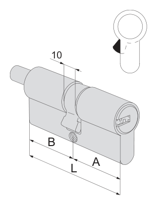

Cylinder dimensions
| Specifications | Dimensions from model documentation |
|---|---|
| Overall length L | 79 mm |
| Side A length | 39.5 mm |
| Side B length | 39.5 mm |
Measure both sides from the fixing screw. Check the cylinder profile, cam and version.
Browse related directorySpecifications
- Key system
- ASIX
- Construction
- Euro-profile cylinder with knob shaft
- Operating configuration
- Knob shaft
- Catalogue nominal size
- 40/40 mm
- Overall length L
- 79 mm
- Side A length
- 39.5 mm
- Side B length
- 39.5 mm
- Catalogue pin count
- 6
- Measurement reference
- Central fixing-screw axis; In the original drawing, B is on the left and A on the right
- Knob supply
- Knob selected separately on request
- Shaft-end position
- End of section B (original drawing)
- Housing and plug material
- Brass
Dimensions and installation orientation
For this model, A=39.5 mm, B=39.5 mm, body L=79 mm; Sections A and B have equal lengths. Tabulated nominal size 40/40 identifies the order; use columns A, B and L for actual lengths.
The original drawing divides the sections at the central fixing-screw axis, with section B on the left and section A on the right. The key end is in section A, and the knob-shaft end in section B; Reversing the two section lengths does not produce the same installation configuration.
Operating construction and matching components
The end of section B has a knob shaft; the knob is optional, so a shaft version must not be understood as a complete cylinder supplied with a knob.
Limitations
- A and B follow the orientation of the manufacturer's original drawing and do not directly designate the inside or outside of the door; check the operating side before installation.
- Catalogue nominal sizes differ from actual measurements; adding nominal sizes must not replace L.
- The original diagram shows only the lengths of the body sections; it is not a product outline, shaft-end machining drawing or installation template.
Sources
CISA English catalogue, PDF page 111 / printed page 107Manufacturer documents are provided in their original language.