
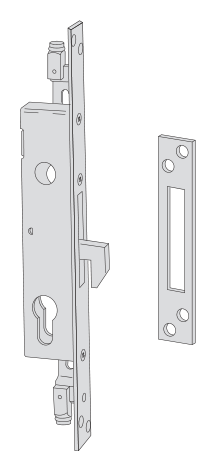
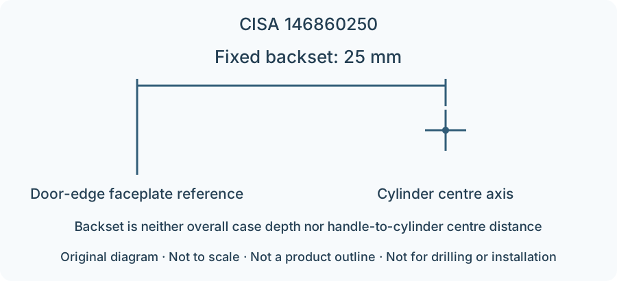
Lock and fitting dimensions
| Specifications | Dimensions from model documentation |
|---|---|
| Backset | 25 mm |
| Faceplate width | 25 mm |
| Spindle specification | 8 mm |
Check the backset, centre distance, faceplate and mounting points against the specific model drawing.
Browse related directorySpecifications
- Product series
- 46860
- Backset
- 25 mm
- Applicable door construction
- Grille door
- Body construction
- Nickel-plated laminated-steel hook bolt
- Faceplate width
- 25 mm
- Case material
- Galvanized steel
- Faceplate material
- Stainless steel
- Spindle specification
- 8 mm
- Additional locking-point interface
- Threaded bushings
- Hook-bolt clearance
- 7.5 mm
Selecting construction and installation dimensions
This row of 46860 has a fixed backset of 25 mm. Check the distance from the door-edge faceplate reference to the cylinder centre axis; overall case depth cannot substitute for it. Laminated-steel hook clearance is 7.5 mm; strike 1.06232.21.0 is also listed; the hook construction engages differently from a straight bolt.
The installation construction of Grille door must match Nickel-plated laminated-steel hook bolt. Additional locking points use threaded bushings; both accessory interfaces and installation positions must match.
Check locking-point positions, door-edge strikes and internal installation space together; equal backsets alone do not establish interchangeability. Check cylinder length and trim on both sides separately for the actual door.
Limitations
- The backset diagram only explains the measurement reference from the faceplate to the cylinder axis; it is not an outline, drilling or installation drawing.
- Check cylinders, extension rods, strikes and other accessories against the specific model; accessories listed in the catalogue as available on request are not standard equipment.
- Series certification or suitability does not establish that any complete door currently meets the corresponding grade.
Sources
CISA 2026 English catalogue, PDF page 179 / printed page 175Manufacturer documents are provided in their original language.